Within Case File
Where in the sky was the object?
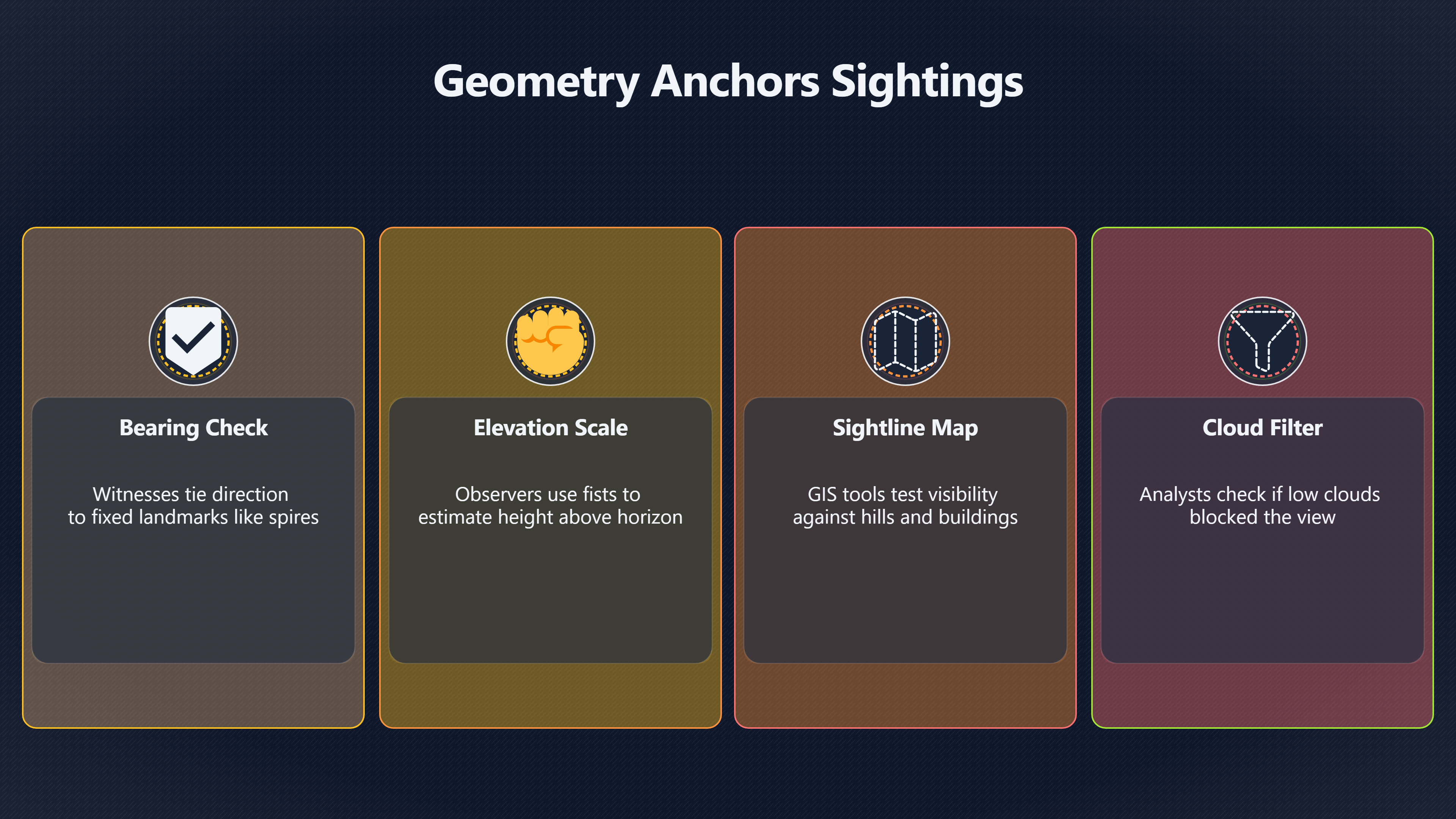
Direction, elevation and landmarks help convert a witness description into a map that can be compared with real sky and ground data.
On this page
- Estimating bearing from landmarks and compasses
- Using elevation angle without false precision
- Mapping sightlines against terrain, clouds and obstructions
Page outline Jump by section
Introduction
A UFO report becomes much more testable when the witness can describe where the object appeared in the sky, not just what it looked like. Bearing and elevation checks turn a story into geometry. Instead of “a bright object over the hills”, investigators can work with “seen from the car park facing west-north-west at roughly 25° elevation, moving left to right above the ridge line”. That change allows AI-assisted investigation systems to compare the report against terrain, aircraft tracks, satellite paths, cloud layers, astronomical objects and camera footage.
 This matters because many apparent anomalies disappear once the viewing geometry is reconstructed properly. Venus low above the horizon, a drone beyond a ridge, landing lights aligned with a valley, or a satellite crossing a gap in cloud can all look extraordinary when direction and angle are vague. Equally, some reports remain difficult to explain after geometric checks because the timing, path or sightline does not fit ordinary traffic or sky objects. The goal is not to prove or dismiss a UFO claim, but to anchor it in measurable space.
Estimating bearing from landmarks and compasses
Bearing is the horizontal direction from the observer to the object, normally measured in degrees clockwise from north. A witness who says “north-west” is already giving more useful information than one who says “over there”, but the strongest reports tie the direction to physical landmarks.
A practical reconstruction usually begins with questions such as:
- Which way were you facing?
- What fixed landmarks were visible?
- Did the object pass above a building, hill, mast or treeline?
- Did it move relative to those landmarks?
- Did it disappear behind anything?
These answers let investigators rebuild the sightline on a map. A church spire, motorway, coastline, mountain ridge or tower can provide a reference line accurate enough for comparison with flight data or astronomy software.
Phone compass readings help, but they should never be treated as exact without caution. Smartphones can be distorted by metal railings, vehicles, magnetic interference and poor calibration. A witness who records “bearing approximately 290°, measured on phone compass” is providing better evidence than someone claiming “exactly 287°” from memory hours later.
In many investigations, relative geometry matters more than perfect precision. If several witnesses independently place an object west of a known ridge line, that already narrows the candidate explanations substantially.
AI-assisted workflows can use these inputs to generate estimated sight cones on a map. Instead of plotting a single impossible “perfect” line, better systems model uncertainty bands. A witness facing “between west and north-west” may produce a 20° directional corridor rather than one razor-thin track.
Landmarks are often stronger than memory alone
Human directional memory is unreliable, especially during surprising events at night. Investigators therefore prioritise stable reference points:
- road orientation
- coastline direction
- railway lines
- hill ridges
- visible stars or the Moon
- aircraft approach paths
- prominent towers or wind turbines
A witness saying “the object hovered directly above the radio mast before moving towards the airport” gives investigators something measurable. If the mast location and observer position are known, the bearing can be reconstructed even if the witness never used a compass.
This is especially important in retrospective cases where reports emerge days later. Memory for colour and motion may drift, but landmark relationships are often retained more accurately.
Using elevation angle without false precision
Elevation describes how high an object appeared above the horizon. An object on the horizon is near 0°. Straight overhead is 90°. Most witnesses cannot estimate exact angles reliably, and investigators should avoid encouraging false precision.
A report saying “about halfway between the horizon and directly overhead” is often more trustworthy than one claiming “47° elevation” unless a measurement tool was actually used.
Astronomy education material commonly teaches rough sky-angle estimation using hands held at arm’s length. A clenched fist spans roughly 10° of sky, while a little finger is close to 1°. [lco.global]lco.globalPositions and Sizes of Cosmic ObjectsIf you extend your hand to arm's length, you can use your fingers to estimate angular distances and… [EarthSky These methods are approximate]earthsky.orgsky measurements degrees arc minutes arc secondsFor example, your fist held at arm's length measures 10 degrees on the sky's dome.Read more…, but they are useful because they create repeatable reference scales that ordinary witnesses can understand.
For UFO investigation work, the key is consistency rather than laboratory accuracy. If a witness says:
- “two fists above the horizon”
- “just above the treeline”
- “lower than the Moon”
- “about level with the aircraft approach lights”
then the observation can be tested against known sky geometry.
Why elevation changes the interpretation
The same bright object can imply very different explanations depending on elevation.
A low-elevation light near the horizon is more likely to involve:
- aircraft landing lights
- planets such as Venus or Jupiter
- atmospheric distortion
- distant towers
- vehicles on elevated roads
- temperature inversion effects
A high-elevation object moving rapidly overhead may fit satellites, meteors or aircraft crossing near the observer.
Elevation also affects perceived motion. Near the horizon, small head movements or perspective effects can make stationary objects appear to drift dramatically. This is one reason bright planets generate recurring UFO reports.
Investigators therefore treat claims like “it shot across the entire sky instantly” carefully. Without angular measurements, witnesses may be describing rapid apparent motion rather than impossible physical speed.
Angular motion is often more useful than guessed speed
Witnesses are usually poor at estimating distance and speed for unknown aerial objects. Angular motion is often more reliable.
[For example:]earthsky.orgsky measurements degrees arc minutes arc secondsFor example, your fist held at arm's length measures 10 degrees on the sky's dome.Read more…
- “crossed from south to west in 12 seconds”
- “remained stationary relative to the chimney”
- “moved one finger-width every second”
These descriptions can later be compared with aircraft tracks, satellite passes or drone performance.
This distinction matters because extraordinary speed claims often collapse once scale uncertainty is recognised. A nearby insect crossing a camera frame can appear faster than a distant aircraft, while a distant aircraft viewed head-on can appear motionless for several minutes.
Mapping sightlines against terrain, clouds and obstructions
Once bearing and elevation are estimated, the sighting can be converted into a line-of-sight problem. This is where geography becomes crucial.
Terrain analysis asks a simple question: could the witness physically see the claimed object from that location?
Modern mapping systems and GIS visibility tools can test this using digital elevation models and line-of-sight analysis. [ArcGIS]doc.arcgis.comArcGISConduct line of sight analysis—3D Workflows | DocumentationA line-of-sight analysis in ArcGIS involves examining the visibility bet… Hills, ridges, buildings and treelines can block or reveal parts of the sky in ways witnesses may not consciously notice.
A classic failure mode in UFO reports is misunderstanding horizon geometry. An aircraft descending behind a ridge may appear to “vanish instantly”. A light emerging from behind cloud gaps may appear to accelerate or change direction.
AI-assisted workflows can automate several checks:
- whether a mountain blocked the claimed sightline
- whether low cloud layers matched the reported disappearance point
- whether a known aircraft route aligned with the observed path
- whether the Moon or Venus sat along the same azimuth
- whether terrain channels created optical illusions

Terrain can radically alter apparent behaviour
Geography affects perception more than many witnesses realise.
Examples include:
- helicopters appearing stationary against distant hills
- aircraft lights blinking through trees
- drones rising from behind ridges
- satellites disappearing into Earth’s shadow
- lights dipping behind terrain contours
A witness may honestly report an object “dropping vertically into the hills” when the geometry actually reflects a normal aircraft descending along a hidden valley approach path.
Viewshed analysis tools used in mapping and planning can help reconstruct these scenarios. These systems model which areas are visible from a given observer position and which are obscured. [ArcGIS]doc.arcgis.comArcGISConduct line of sight analysis—3D Workflows | DocumentationA line-of-sight analysis in ArcGIS involves examining the visibility bet…
In UFO case work, this is especially valuable when multiple witnesses report the same event from different locations. If their reported bearings intersect in physically impossible ways, the accounts may involve separate objects, memory distortion or inaccurate direction estimates. If the sightlines converge consistently, the geometry strengthens the case reconstruction.
Clouds, haze and perspective distortions
Cloud cover is one of the most overlooked geometric factors in UFO reports.
Low clouds can create false impressions of altitude and distance. A light reflecting from cloud bases may appear huge and elevated. Searchlights, industrial lighting and illuminated drones can produce moving patches that seem detached from any visible source.
Cloud gaps also create misleading motion cues. A satellite passing through alternating cloud and clear sky can appear to blink, jump or manoeuvre.
Perspective effects become stronger at night because the sky lacks depth references. Without visible terrain or stars, witnesses often overestimate object size and underestimate distance.
This is why investigators ask:
- Was the horizon visible?
- Were stars visible around the object?
- Did clouds pass in front of or behind it?
- Did the object illuminate cloud?
- Could you judge its height relative to known structures?
These questions help separate physical motion from visual interpretation.

Why investigators avoid “exact” geometry from weak observations
One of the biggest mistakes in UFO analysis is turning uncertain witness impressions into fake precision.
A report may begin as:
“I think it was somewhere south-west and fairly high.”
By the time it reaches online discussion forums, it becomes:
“Object observed at bearing 231° and elevation 42°.”
That transformation can create misleading certainty.
Good investigation practice keeps uncertainty visible at every stage. Bearings should often be expressed as ranges. Elevation estimates should include confidence notes. Witness recollections should remain distinct from measured data.
AI systems are especially vulnerable to overconfidence because they can combine weak inputs into highly polished visualisations. A neat-looking trajectory map can hide the fact that the underlying witness geometry was vague.
The strongest case files therefore preserve the difference between:
- measured direction
- estimated direction
- inferred direction
- reconstructed direction
That distinction is essential when comparing sightings against aircraft databases, astronomical simulations or satellite ephemerides.
Turning geometry into a testable UFO case
A structured geometry check usually produces one of four outcomes.
The geometry strongly fits a known object
Examples include:
- Venus at the reported azimuth and elevation
- a commercial aircraft on a matching approach path
- a Starlink satellite train crossing the same sky corridor
- a drone launch site aligned with the witness bearing
In these cases, the witness may still have seen something unusual-looking, but the geometry supports a conventional explanation.
The geometry partly fits but leaves gaps
A witness may correctly describe an aircraft path but also report behaviour not supported by tracking data. Or the direction may match a satellite pass while the duration does not.
These are often the most common real-world outcomes.
The geometry cannot be reconstructed reliably
Many reports fail here because the witness cannot establish direction, elevation or timing with enough confidence.
Such cases are not necessarily false. They are simply weakly testable.
The geometry remains difficult to explain
Occasionally, a sightline reconstruction does not align cleanly with known aircraft, astronomical objects, terrain masking or weather conditions.
Even then, geometry alone does not prove something extraordinary occurred. It only establishes that the event remains unresolved after basic spatial checks.
That distinction is central to evidence-led UFO investigation. The purpose of bearing and elevation analysis is not to force a conclusion, but to narrow the range of plausible explanations using measurable relationships between observer, sky and terrain.
Endnotes
-
Source: lco.global
Link: https://lco.global/spacebook/sky/using-angles-describe-positions-and-apparent-sizes-objects/ -
Source: earthsky.org
Title: sky measurements degrees arc minutes arc seconds
Link: https://earthsky.org/astronomy-essentials/sky-measurements-degrees-arc-minutes-arc-seconds/Source snippet
For example, your fist held at arm's length measures 10 degrees on the sky's dome.Read more...
-
Source: doc.arcgis.com
Link: https://doc.arcgis.com/en/3d/workflows/analysis/conduct-line-of-sight-analysis.htmSource snippet
ArcGISConduct line of sight analysis—3D Workflows | DocumentationA line-of-sight analysis in ArcGIS involves examining the visibility bet...
Additional References
-
Source: usgs.gov
Link: https://www.usgs.gov/educational-resources/topographic-mappingSource snippet
Topographic Mapping | U.S. Geological SurveyThe feature that most distinguishes topographic maps from maps of other types is the use of c...
-
Source: facebook.com
Link: https://www.facebook.com/GeniusClubb/posts/measuring-the-night-sky-by-hand/1506332947519205/Source snippet
Measuring the Night Sky by HandMeasure distances in the night sky with your hands ✋ For starters, hold your hands at arm's length in fron...
-
Source: sk.sagepub.com
Link: https://sk.sagepub.com/ency/edvol/download/geography/chpt/digital-terrain-model.pdfSource snippet
SAGE KnowledgeEncyclopedia of GeographyTwo fundamental parameters in visibility analysis can also be computed from a DTM, that is, point...
-
Source: timeanddate.com
Link: https://www.timeanddate.com/astronomy/measuring-the-sky-by-hand.htmlSource snippet
A Handy Guide to Measuring the SkyA “Handy” Way to Measure Distances: Hold your hand at arm's length and close one eye. It is important t...
-
Source: ryancbinns.com
Link: [https://www.ryancbinns.com/assets/production/pdfs/flying/lessons/area_02/task_c_-visual_scanning_and_collision_avoidance.pdf](https://www.ryancbinns.com/assets/production/pdfs/flying/lessons/area_02/task_c-_visual_scanning_and_collision_avoidance.pdf)Source snippet
Visual Scanning and Collision AvoidanceThis lesson introduces pilots to the concepts behind proper visual scanning and collision avoidanc...
-
Source: youtube.com
Link: https://www.youtube.com/watch?v=rxyink0U_fQSource snippet
Military Tools for ArcGIS: Visibility for AnalystsLearn how to quickly create multiple types of visibility graphics, such as linear and r...
-
Source: ncsciencefestival.org
Link: https://ncsciencefestival.org/wp-content/uploads/sites/1442/2025/08/SSP_Handy-Way-to-Measure-the-Sky.pdfSource snippet
Note that you can use two hands to combine measures, such as in this photo showing 10° fist width + 25° thumb...Read more...
-
Source: hfcc.dot.gov
Title: zz FAA General Guidance Doc Chapter 02 Section 03
Link: https://hfcc.dot.gov/publications/docs/GeneralGuidance/zz_FAA_GeneralGuidanceDoc_Chapter_02_Section_03.pdfSource snippet
2013 – CHG 1 2.3 Field-of-View1 Nov 2013 — General. • Each flight, navigation, and powerplant instrument for use by any pilot must be pla...
-
Source: researchgate.net
Link: [https://www.researchgate.net/publication/241370852%27Is_pilots%27_visual_scanning_adequate_to_avoid_mid-air_collisions%27](https://www.researchgate.net/publication/241370852%27Is_pilots%27_visual_scanning_adequate_to_avoid_mid-air_collisions%27)Source snippet
ndow (OTW) visual scanning pattern to avoid traffic conflicts, however little research...Read more...
-
Source: reddit.com
Link: https://www.reddit.com/r/Astronomy/comments/1fi3hhv/hand_astronomy_inaccuracy/
Amazon book picks
Further Reading
Books and field guides related to Where in the sky was the object?. Use these as the next step if you want deeper reading beyond the article.
eBay marketplace picks
Marketplace Samples
Example marketplace items related to this page. Use the search link to explore similar finds on eBay.

Topic Tree